Mechanisms · Mechatronics · CAD · Control
Five-BarMechatronic System
A two-degree-of-freedom five-bar robotic manipulator developed through mechanical design, CAD, kinematic modelling, physical prototyping, electronics integration and simulation-based control.
View Technical Report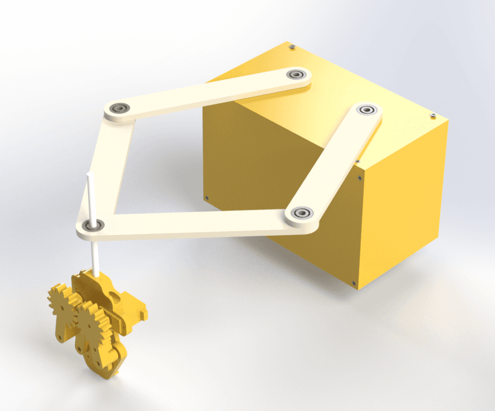
Concept Development
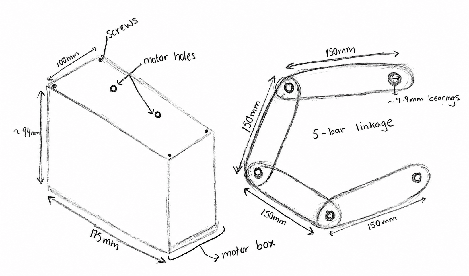
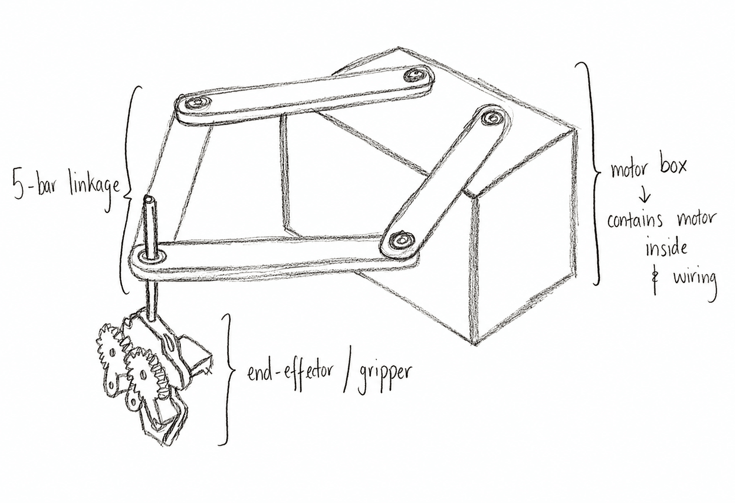
The early concept stage established the five-bar linkage arrangement, motor positions, base geometry and end-effector location. The design was refined around a compact base-mounted layout so the actuators could remain fixed while the linkage generated planar two-degree-of-freedom motion.
- 01Base-mounted motors
- 02Reduced moving inertia
- 03Symmetric planar motion
- 04Motor and wiring clearance
- 05End-effector development
CAD & Mechanical Design
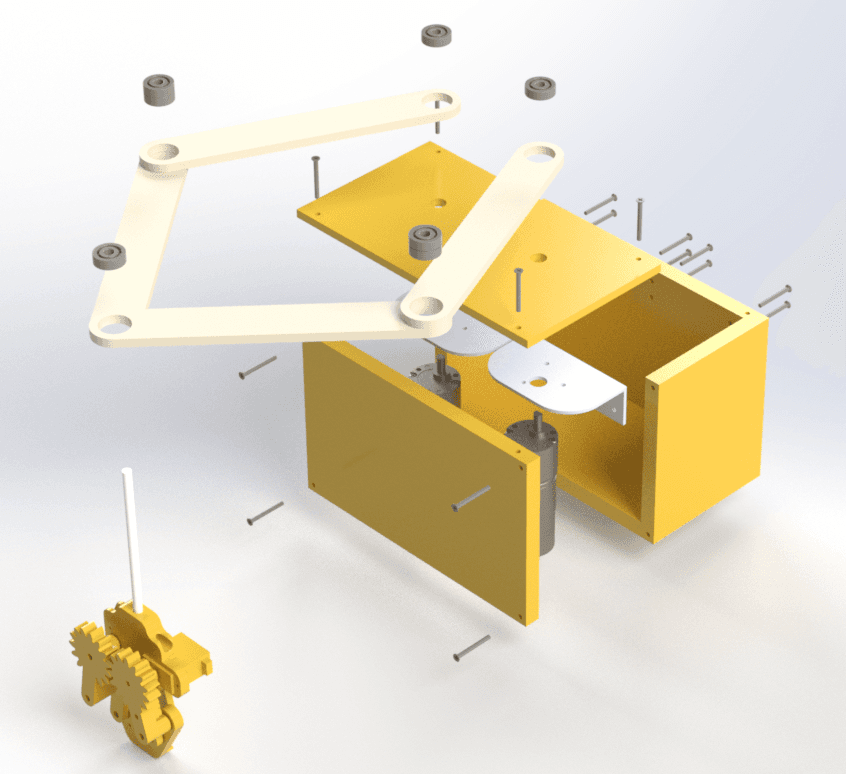
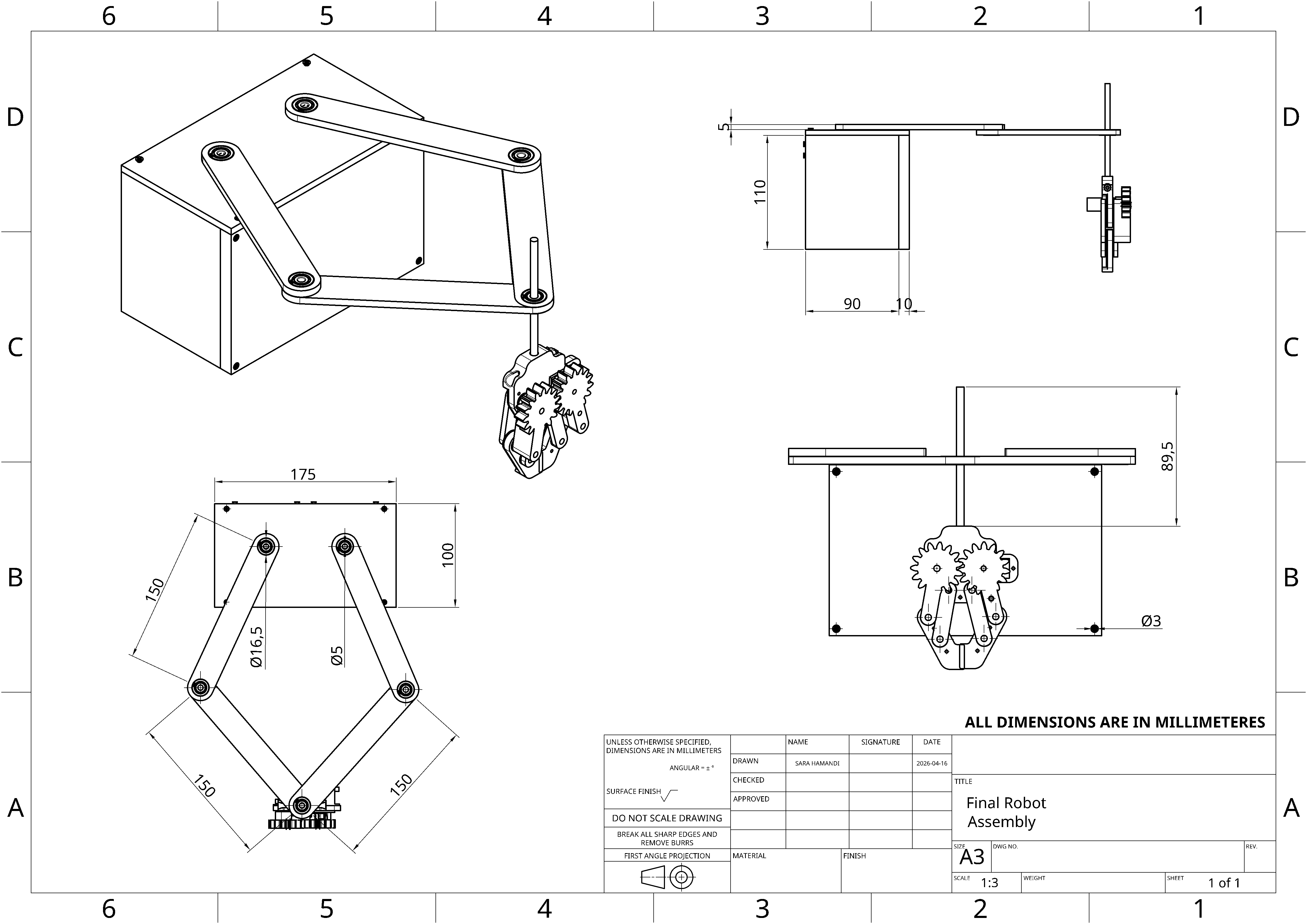
The CAD model developed the five-bar concept into a complete mechanical assembly, allowing the linkage geometry, actuator placement, bearings, base structure and end-effector region to be coordinated before manufacture.
Design trade-offs included balancing symmetry and compactness against wiring access, stiffness, backlash and manufacturing tolerances. The final concept used base-mounted actuation, bearing-supported joints and lightweight printable structural components.
Kinematic Modelling
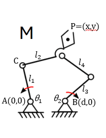
The robot was modelled as a planar five-bar closed-chain mechanism with two grounded revolute joints and one common end-effector point. Forward kinematics were used to calculate the end-effector position from the two actuated joint angles, while inverse kinematics calculated the required joint angles for a desired Cartesian position.
Physical Build & Electronics
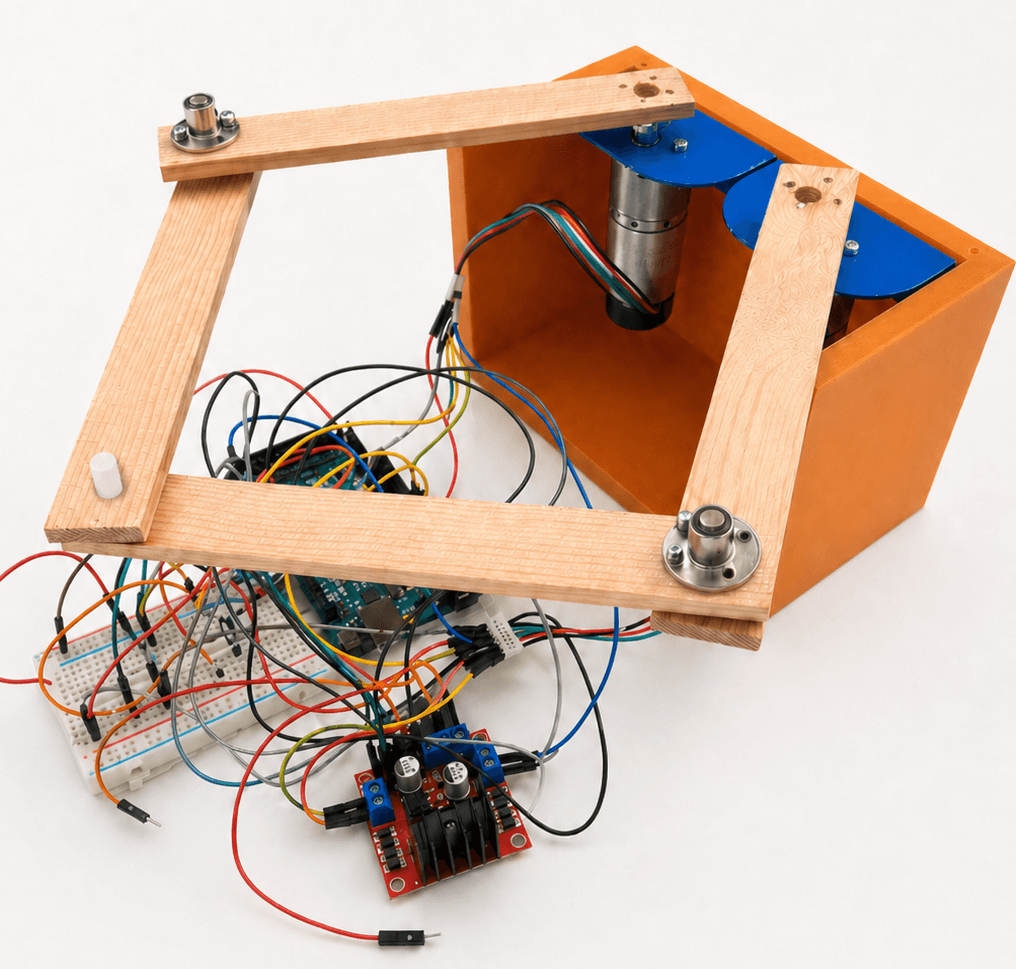
The physical prototype combined the five-bar linkage with two base-mounted EMG30 geared motors, an Arduino Mega 2560, L298N motor driver, encoder-capable actuation and a fabricated mechanical structure.
Assembly highlighted the practical influence of joint clearance, shaft alignment, screw length, linkage accuracy, backlash, wiring complexity and structural stiffness.
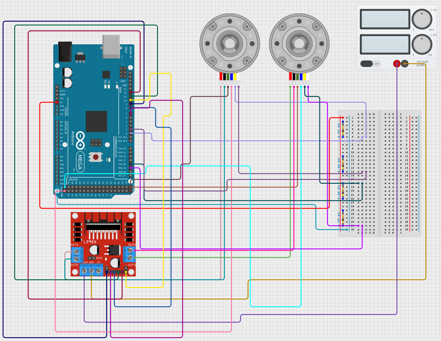
- Arduino Mega 2560
- Control and I/O platform
- 2 × EMG30 Motors
- Geared DC motors with encoders
- L298N Driver
- Bidirectional motor interface
- Encoder Feedback
- Intended for future hardware closed-loop control
Simulation & Control
Joint position control was investigated in MATLAB/Simulink using two independent PID loops acting on simulated motor-plant models. The control architecture was then connected to the inverse- and forward-kinematic models to evaluate coordinated Cartesian point regulation.
The simulated end effector converged to the desired Cartesian target, although the transient path was curved because the two joints had different rise, overshoot and settling characteristics.
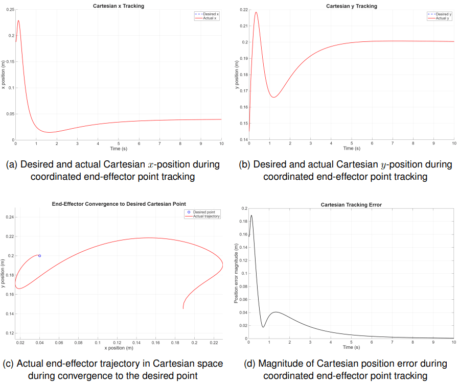
The end effector converged to the desired point, but the differing joint transients produced temporary Cartesian path deviation.
Final Outcome
The robot was developed as a two-degree-of-freedom five-bar robotic manipulator, progressing from concept through CAD, kinematic modelling, physical assembly, electronics integration and simulation-based control. The project demonstrated the relationship between mathematical modelling and real mechanical behaviour, while highlighting the importance of stiffness, joint accuracy, backlash reduction, wiring quality and coordinated joint response.
Future development would focus on physical encoder-based PID implementation, reduced mechanical backlash and full Cartesian trajectory tracking.